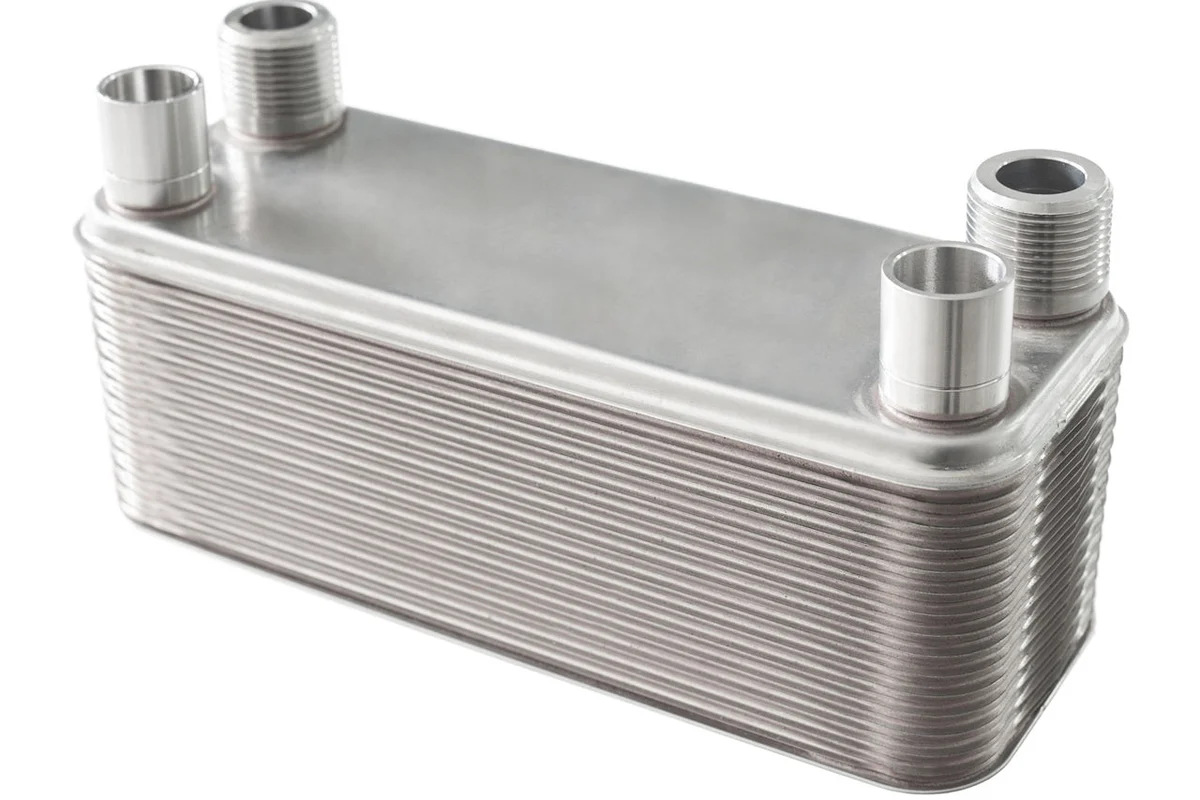
In high-reliability sectors such as aerospace, power equipment, heat exchangers, and precision machinery, brazed joints are frequently critical load-bearing components rather than mere assembly details. If an engineer is evaluating a design drawing on which a joint “meets the strength standard,” then of far greater importance than determining whether it has attained adequate tensile or shear strength from a data sheet value is determining if it will safely resist multiple axial loads.
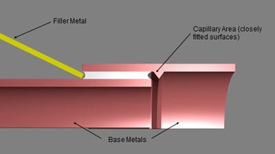
While joint types such as welding or bolting involve a relatively thick layer of filler material, in brazing, it is very thin and heavily constrained by other materials. Because of such distinct characteristics and corresponding stress, it is not feasible to design with conventional criteria and strength properties. To determine if a brazed joint satisfies a given standard, one must assess it as a structure, not simply a material specimen.
Why Traditional Strength Criteria Are Insufficient
Traditional failure theories like maximum normal stress, Tresca (maximum shear), and von Mises were developed for homogeneous, isotropic metals under relatively uniform stress states. Brazed joints do not satisfy these assumptions:
Non-homogeneous structure
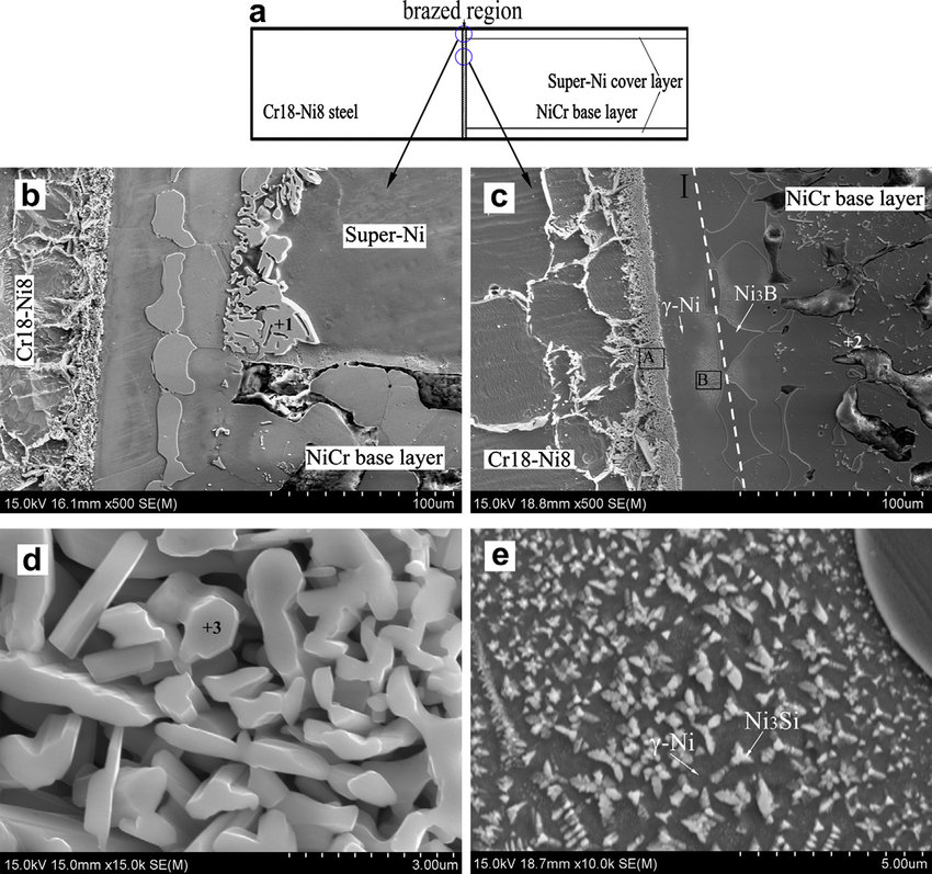
It differs both chemically and mechanically from each base metal. Property variation over microns arises due to intermetallic formation, dilution, and microstructural gradients.
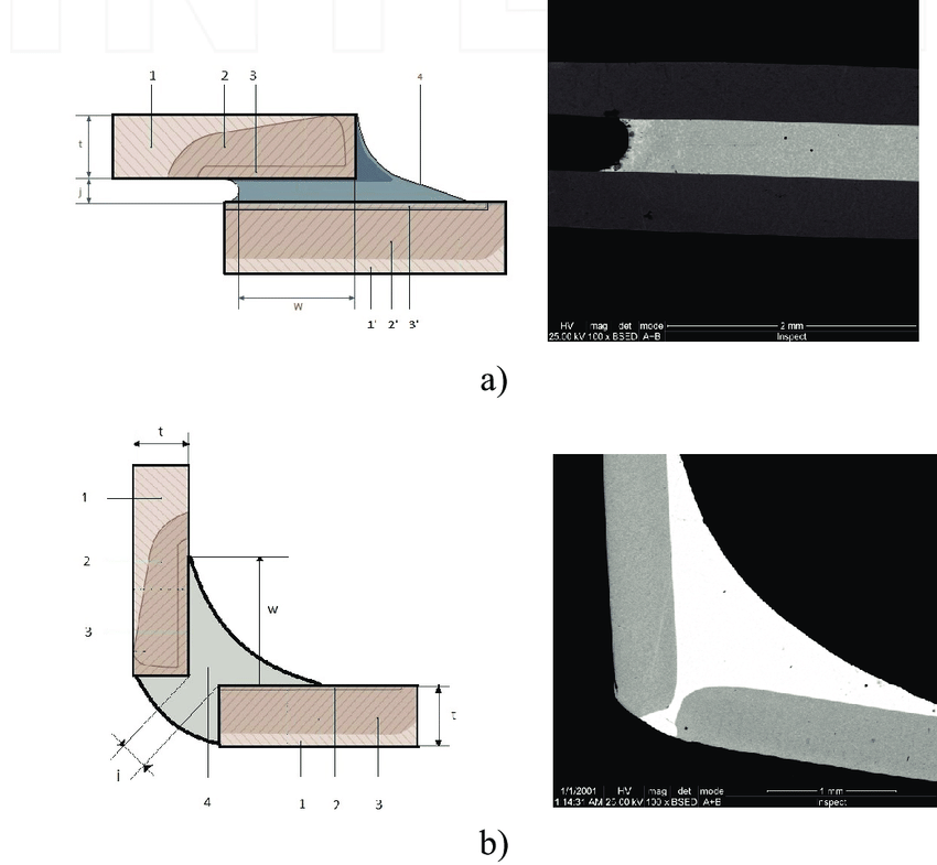
Extreme geometric restrictions
As we know, the braze thickness is typically less than 100 μm, while the joint width may be several millimetres. This high aspect ratio suppresses plastic flow and creates triaxial stress states.
Different failure mechanisms
In lap shear, the joint behaves in a ductile mode and can yield before fracture. In butt tension or compression, the filler metal is under near-hydrostatic stress and fails in a quasi-brittle mode, even though the filler alloy itself is ductile in bulk form.
Due to this, the application of a simple limit on tensile strength to a brazed joint results in unsafe overestimation, especially under combined loading.
Stress the Brazed Joint as a Structural Unit.
An important finding of recent studies about brazing is that the joint should be viewed as a structural unit, and not a thin layer of topping metal that has taken on the characteristics of bulk. The real carrying capacity is determined by:
- Braze gap and joint geometry
- Dilution from base metals
- The formation of intermetallic compounds.
- Remaining stresses due to cooling.
- Outer material degree of constraint.
Because these factors cannot be effectively modeled through small-scale material tests, the most plausible approach is to establish the permissible strengths of the joint as a system in the form of standard tensile and lap shear test (e.g., per AWS C3.2) and subsequently implement a conservative interaction model of combined loading.
Coulomb–Mohr Interaction for Brazed Joints
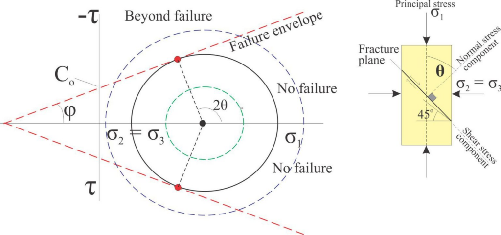
A failure criterion based upon the Coulomb–Mohr concept provides a simple and physically significant structure for highly constrained joints exhibiting quasi-brittle behavior. In its standardized structure for brazed joints, it can be written as
Rσ+Rτ=1R_\sigma + R_\tau = 1Rσ+Rτ=1
where we see:
- Rσ=σ/σ0R_\sigma = \sigma / \sigma_0Rσ=σ/σ0 is the tensile stress ratio
- Rτ=τ/τ0R_\tau = \tau / \tau_0Rτ=τ/τ0 is the shear stress ratio
- σ0\sigma_0σ0 is the allowable tensile strength from butt-joint tests
- τ0\tau_0τ0 is the allowable shear strength from lap-shear tests
Such allowables do not relate to material properties but instead reflect performance of a brazed joint system at two limiting states: tension and shear. The linear interaction equation describes a conservative lower-bound failure envelope. Any combination of tensile and shear stresses that satisfy
Rσ+Rτ<1R_\sigma + R_\tau < 1Rσ+Rτ<1
lies within the safe region for static loading.
Application of Failure Assessment Diagrams
The interaction equation can be given as a powerful design tool in terms of an FAD: In this diagram:
- The horizontal axis represents normalized tensile stress RσR_\sigmaRσ
- The vertical axis represents normalized shear stress RτR_\tauRτ.
- The line Rσ+Rτ=1R_\sigma + R_\tau = 1Rσ+Rτ=1 defines the conservative failure boundary
Practical engineering applications include:
Determining Joint Allowables
On the basis of standardized butt tensile and lap shear tests, preferably using statistically conservative A-basis values.
Service emphasizes calculation
Determine the maximum values of σ and τ in the brazed area because of design loads by FEA.
Draw the operating point
The results of the calculated stress ratios are then graphed on the FAD.
Margin of Safety Analysis
Margin of Safety The distance between the operating point and the failure line determines the available MS and this technique offers the evaluation of complex multi-axial states of stress by means of a simple engineering criterion that is transparent.
Importance of Margin of Safety
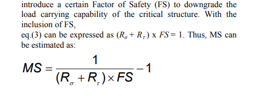
Meeting a “standard strength value” is inadequate for critical structures. Manufacturing variability, braze defects, residual stresses, and inspection limitations all act to decrease real load capacity. Therefore, a Factor of Safety (FS) must be incorporated:
Rσ+Rτ)×FS≤1
The Margin of Safety is then:
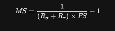
A positive MS shows that the joint meets requirements with sufficient conservatisms. This method places brazed joint evaluation in line with accepted aerospace and pressure-vessel design practice.
A Warning: Shear Strength Interpretation from Lap Tests
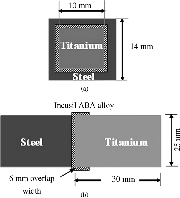
One of the most important practical considerations is the length of the lap and the resulting dependence of the measured shear strength on the length of the lap. Experimental evidence has shown that:
Short overlap specimens (such as 1T, where T is base metal thickness) usually fail in the braze and provide reasonable joint shear strength.
The longer the overlaps, the more they tend to shift, breaking into the base metal, which gives an artificially high apparent shear strength. Longer overlaps often lead to base metal failure, preventing the measurement of the true braze shear strength and potentially masking the non-uniform stress distribution (stress concentration at the joint edges)
Therefore, it must be based on the lowest representative strength value found for a given set of overlap lengths, rather than the highest test result. The use of the inflated shear allowables may result in non-conservative FAD values.
Influence of Defects and Inspection Restrictions
Even when interaction criteria and conservative allowables are employed, internal defects such as lack of fill, voids, and trapped flux can significantly reduce the strength of the joint. Validation tests of complex geometries have shown that specimens with large areas of unbrazed joints may fail well within the nominal “safe” area predicted by average property models.
This reality underlines the importance of: Conservative statistical allowables: A-basis or B-b Additional safety factors for critical assemblies Strict process control and nondestructive examination
Is the strength of the brazed joint in accordance with the standard?
From the perspective of industrial engineering, the answer is
A brazed joint satisfies the strength standard only if
- The allowable tensile and shear strengths are established from representative standardized tests.
- Simultaneous service stress conditions are taken into account, rather than just single-mode service loads
- A conservative interaction criterion, such as Coulomb-Mohr equation, is used.
- The failure assessment diagram verifies that the operating stress point lies well within the safe area.
- A suitable Factor of Safety and Margin of Safety are introduced to account for defects, variability, and inspection limits.
- A simple comparison between the calculated stress value and a single tensile or shear strength value cannot determine a sufficient strength evaluation for highly constrained brazed joints.
Appropriate compliance with engineering standards needs a system-level, multi-axial, and margin-based assessment.
Engineering Perspective Final
Engineering Perspective In contemporary high-reliability design, the answer to the question is no longer “What is the strength of the filler metal?” but instead: “What is the safe load-carrying capability of the brazed joint as an integrated, constrained structural element under combined stresses?”
By employing joint-level allowables, Coulomb-Mohr interaction, Failure Assessment Diagrams, and conservative Margin of Safety analysis, the engineer can confidently answer this question and ensure that a brazed joint not only meets the nominal standard but also satisfies the reliability requirements of critical industrial service.